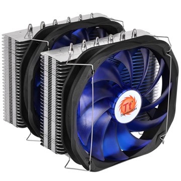
- Ultimate Over-clocking Design Structure, support up to 250W.
- The Combination of VR and PWM Control Function Fan.
- Universal Socket Compatibility.
![]()
Ultimate Over-clocking Design Structure, support up to 250W
- Dual tower heat-sink with 0.4mm aluminum fins provide large surface for heat
dissipation.
- 6 x Ø6 mm-U-shape copper heat pipes accelerate heat conductivity.
- Mirror-finished copper base, provide perfect contact with CPU.
- Premium thermal grease maximizes heat transfer from the CPU onto the copper
base for faster dissipation.
The Combination of VR and PWM Control Function Fan
Dual 14cm high performance blue blade designed fans, spins from 1,200 to
1,800RPM.
Combination of VR and PWM functions, switchable upon user’s preferences.
Tool-less and Easy installation design for quicker disassemble and assemble the
fan module.
Universal Socket Compatibility & Accessory Package
All-in-one back-plate design, support all Intel and AMD platform
Universal socket support :
Intel: LGA 2011, 1366, 1155, 1156, 775
AMD: FM1, AM3+, AM3, AM2+, AM2

Intel Motherboard Installation
| Step 1 | Step 2 |

|

|
| Insert the four long screws through the back-plate into the four holes on the motherboard and secure them with the four plastic spacers evenly. | Put the two Intel mounting bars along with the four long screws and secure them with the four nuts. |
| Step 3 | Step 4 |

|

|
| For LGA2011: Screwing the LGA 2011 screw onto motherboard tightly and put the two Intel mounting bars on the LGA 2011 screws. Fasten the four nuts onto the mounting bars tightly. | Install the fan clips onto the heat-sink separately |
| Step 5 | Step 6 |

|

|
| Applying a thin layer of thermal grease onto the CPU. | Screw the heat-sink onto the motherboard with the mounting plate tightly. |
| Step 7 | Step 8 |

|

|
| Fix the two fans onto the heat-sink with fan clips separately. | Connect two fan cords to the controller close to the VR Knob. Link the power cord to the CPU FAN slot and the right slot of the controller. |
| Step 9 | |

|
|
| Connect the 4-pin wire of controller to the motherboard’s CPU fan connector. Installation is done. |
AMD Motherboard Installation
| Step 1 | Step 2 |

|

|
| Insert the four long screws through the back-plate into the four holes on the motherboard and secure them with the four plastic spacers evenly. | Put the two AMD mounting bars along with the four long screws and secure them with the four nuts. |
| Step 3 | Step 4 |

|

|
| Install the fan clips onto the heat-sink separately. | Applying a thin layer of thermal grease onto the CPU. |
| Step 5 | Step 6 |

|

|
| Screw the heat-sink onto the motherboard with the mounting plate tightly. | Fix the two fans onto the heat-sink with fan clips separately. |
| Step 7 | Step 8 |

|

|
| Connect two fan cords to the controller close to the VR Knob. Link the power cord to the CPU FAN slot and the right slot of the controller. | Connect the 4-pin wire of controller to the motherboard’s CPU fan connector. Installation is done. |
| P/N | CLP0587 |
|---|---|
| ZGODNOŚĆ | Intel LGA 2066/2011-3/2011/1366/1156/1155/1151/1150/775 AMD FM2/FM1/AM3+/AM3/AM2+/AM2 |
| Wymiary | 148.2(L) x 151(W) x 160(H) mm (2 Fans) |
| Heatpipe | 6mm x 6 PCS |
| Connector | 4 Pin |
| Rozmiar wentylatora | 140(L) x 140(H) x 25(W) mm |
| Prękość obrotowa wentylatora | 1200 ~ 1800 RPM |
| Rated Voltage | 12 V |
| Prąd znamionowy | 0.5 A |
| Zasilanie wejściowe | 7.2 W |
| Maksymalny przepływ powietrza | 106.2 CFM |
| Static Pressure | 2.34 mmH2O |
| POZIOM HAŁASU | 38 dBA ~ 18dBA |
| Life time/Fan Life time | 100,000 Hours |
| Cooling Power | 250W |
| Waga | 1,230g |
| Gwarancja | 10 Years |
User Manual
- Nazwa pliku
- Opis
- Rozmiar
- Version
- Release Date


